


Industrial Control Panel
The servo control panel, also referred to as a servo panel or servo motor control panel, integrates a servo drive with the necessary electrical equipment and circuit components. It enabling precise position control, speed regulation, and torque management of servo motors. By combining advanced motion control algorithms with stable motor control panel design, it provides reliable operation within a motor control cabinet or larger motor control center panel (MCP). Our product’s intuitive user interface, energy-saving capabilities, and robust architecture make it an ideal solution for diverse manufacturing equipment, offering an efficient and scalable function of modern servo motor control panels.It applies to industrial robotics, CNC machinery, packaging/printing/textile equipment, semiconductors, medical devices, AS/RS, and new energy vehicles.
Infraswin Energy provides comprehensive, end-to-end solutions, from circuit design to complete cabinet integration, ensuring that every control system is customized to fit your equipment and processes. With full production capabilities, we adhere strictly to customer demand, delivering high-end performance that meets the highest industry standards. Our solutions are backed by UL 508A and CE certifications, guaranteeing safety and compliance with global regulations.
Overview
Applicable standards
UL 508A
IEC61000-4 《Amendment 1-Electromagnetic compatibility(EMC)》
Product Overview
Feature
Product Performance Standards
GB/T 16439-2024: General Technical Requirements for AC Servo Systems
Dielectric Performance Test | System Function Test | Operating Range Test | Temperature Rise Test | Position Tracking Error Test | Torque (or Thrust) Ripple Coefficient Test | Bandwidth Test | Static Stiffness Test | Positioning Settling Time Test | Mechanical Vibration Test | Vibration Test | Shock Test | Electromagnetic Immunity Test (Anti-disturbance Test) | Protection Degree Test (IP Code Test)
IEC 60204-1:2021: Safety of machinery - Electrical equipment of machines - Part 1: General requirements
1. Power Supply and Protection
2. Protection Against Electric Shock
3. Control Circuits and Functions
4. Wiring and EMC
5. Drive and Motor Components
6. Functional Safety Integration
7. Documentation and Marking
8. Verification and Testing
IEC 61010-1:2017: Safety requirements for electrical equipment for measurement, control, and laboratory use - Part 1: General requirements
1. Scope and Basic Principles
2. Fundamental Protection
3. Protection Against Electric Shock
4. Insulation and Spacings
5. Overcurrent and Overtemperature Protection
6. Mechanical Hazards
7. Radiation and Chemical Hazards
8. Marking and Documentation
9. Testing and Verification
IEC 61000-6-2:2016: Electromagnetic compatibility (EMC) - Part 6-2: Generic standards - Immunity standard for industrial environments
| Test Item | Applicable Port | Typical Test Level (Industrial Environment) | Performance Criteria |
| Electrostatic Discharge | Enclosure, operator interfaces | ±4 kV contact discharge, ±8 kV air discharge | Servo drive and control panel must operate normally; temporary effects (e.g. encoder signal disturbance) allowed but system must recover automatically (Class A/B). |
| Radiated RF Electromagnetic Field | Whole equipment (enclosure) | 80 MHz–2.7 GHz, 10 V/m, AM 1 kHz/80% | No loss of motion control, positioning accuracy, or logic functions allowed. |
| Conducted RF Immunity | Power, I/O, communication lines | 150 kHz–80 MHz, 10 Vrms, AM 1 kHz/80% | Data communication, drive control signals, and feedback loops must remain functional. |
| Electrical Fast Transient/Burst | Power port: ±2 kV; I/O ports: ±1 kV | Pulse repetition: 5 kHz | Temporary effects allowed (e.g. motor torque ripple), but servo must recover automatically without uncontrolled motion. |
| Surge | Power port: ±2 kV (common mode), ±1 kV (differential); Signal ports: ±1 kV | Waveform 1.2/50 µs | Servo power stage and I/O must withstand surges without drive shutdown or uncontrolled motor movement. |
| Voltage Dips and Interruptions | Power port | 0% Un for 0.5 cycle; 40% Un for 10 cycles; 70% Un for 25 cycles; 0% Un for 250 cycles | Servo must recover automatically after dips/interruptions; no permanent loss of configuration or safety function. |
| Power Frequency Magnetic Field | Whole equipment | 30 A/m continuous | Servo system must operate normally under industrial magnetic fields without loss of position or speed control. |
| Voltage Variations | Power port | ±10% voltage variation | Servo drive must remain stable; no uncontrolled stop, reset, or loss of motor torque allowed. |
Application
Servo Control Panel is widely used in industrial automation fields, such as industrial robots, CNC, packaging, printing, textile machinery, semiconductor, medical, automated warehousing and new energy, etc.
Keep in Touch
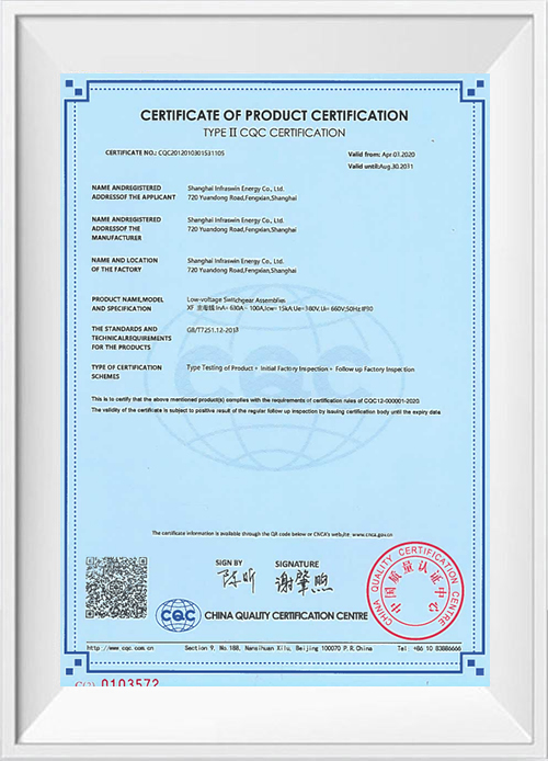
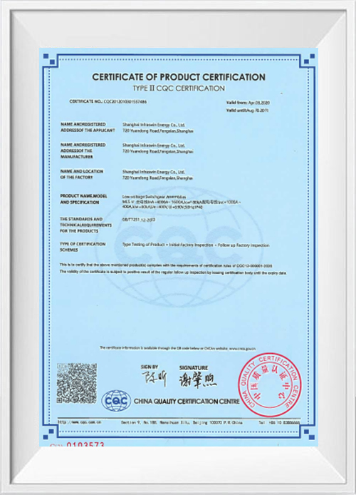
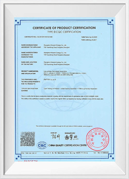
Certificates


Company Profile

In 2002, Mr. Zhu Ning, the founder, started his business in China. In 2009, Shanghai Infraswin Energy Co., Ltd. was established. Infraswin is China Servo Control Panel suppliers and OEM/ODM Servo Control Panel company, a high-tech enterprise with 37 patents, integrating R&D, design, manufacturing, and sales. Our company was successfully listed on the National Equities Exchange and Quotations (NEEQ) in 2017. The stock is abbreviated as Infraswin Energy, with the stock code 871504.
Infraswin specializes in intelligent power distribution, as well as comprehensive energy management and automation control equipment integration.
Infraswin is situated at No. 720, Yuandong Road, Fengxian District, Shanghai. Our power distribution and automation control equipment have received CE and UL certifications and comply with China's Guobiao (GB) national standards.
Our main customers include prominent global companies such as Rittal (Germany), Rockwell (United States), Siemens (Germany), ABB (Switzerland), Panasonic (Japan), and GEA (Germany). Additionally, we are proud to be the main supplier of electrical equipment for Shanghai DISNEYLAND as an Original Equipment Manufacturer (OEM).
Factory area(㎡)
Founded in
Project cases
Employees
News Center
Industry News
Zero-Carbon Parks: Blueprint for a Green Future2026-03-16
Industry News
PLC Maintenance: Practical Steps to Reduce Downtime2026-03-13
Industry News
Power Distribution Center: Types, Sizing & Maintenance Guide2026-03-06
Your one-stop supplier for energy management solutions.
Products
Contact Us
720 Yuandong Road, Fengxian District, Shanghai, China
+86-19101772387
+86-19101772387
info@infraswin.com
 English
 中文简体
中文简体
 Español


