2026-04-14
TN-C, TN-S, and TN-C-S systems are three common grounding types in low-voltage power distribution systems. Their core difference lies in how the neutral (N) conductor and the protective earth (PE) conductor are combined. The specific comparisons are as follows:
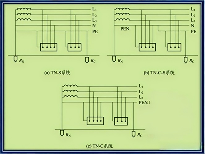
Core Feature: The N conductor and PE conductor are combined throughout into a single PEN conductor, forming a three-phase four-wire system (3 phase conductors + 1 PEN conductor).
Wiring Logic: The power source neutral point is directly grounded. Exposed conductive parts of equipment are directly connected to the PEN conductor, which simultaneously serves both as the neutral conductor for working current and as the protective earth conductor.
Core Feature: The N conductor and PE conductor are completely separated from the power source neutral point onward, forming a three-phase five-wire system (3 phase conductors + 1 N conductor + 1 PE conductor).
Wiring Logic: The power source neutral point is directly grounded. The N conductor carries working current, while the PE conductor is dedicated solely to equipment enclosure protective earthing. The two conductors remain independent and are never mixed.
Core Feature: The TN-C structure is used in the front section, switching to a TN-S structure in the rear section — a hybrid approach.
Wiring Logic: From the power source to the building entry point, the N and PE conductors are combined into a PEN conductor. After entering the building and undergoing repeated earthing, the PEN conductor is separated into independent N and PE conductors. Once separated, they must never be recombined.
Lowest safety. The PEN conductor carries both working current and fault current. Under unbalanced three-phase loads, voltage drop occurs on the PEN conductor, causing equipment enclosures to become live. If the PEN conductor breaks, equipment enclosures become directly live, presenting a very high electric shock risk.
Highest safety. The PE conductor carries current only during a fault; under normal operation, it carries no current, and equipment enclosures remain at zero potential. Even if the N conductor is disconnected, the PE conductor still provides protection, resulting in very low electric shock risk.
Medium safety. The front-section PEN conductor carries risks of voltage drop and breakage, but after separation into an independent PE conductor in the rear section, safety on the load side approaches that of TN-S, with overall risk lower than TN-C.
Poor immunity. Working current on the PEN conductor generates electromagnetic interference, which can easily be conducted to equipment, affecting precision devices.
Strong immunity. The PE conductor carries no working current, so no electromagnetic interference occurs. Working current on the N conductor does not couple into the PE conductor, making this system suitable for locations requiring high power quality.
Medium immunity. The front-section PEN conductor introduces interference, but the rear-section independent PE conductor provides good immunity, though overall it is weaker than TN-S.
Lowest cost. Only four conductors need to be installed, saving conductor material and installation space, with the lowest installation difficulty.
Highest cost. Five conductors must be installed, increasing conductor cost and space requirements, with greater installation difficulty.
Medium cost. The front section follows TN-C to save cost; the rear section adds a PE conductor. Overall cost is lower than TN-S, with installation difficulty between the two.
Fault Current: In the event of a fault (e.g., live conductor touching the enclosure), fault current returns via the PEN conductor. The current is large enough to trigger overcurrent protection devices to trip.
Protection Limitations: If the PEN conductor breaks, fault current cannot return properly, and protection devices may fail. Residual current devices (RCDs) are ineffective against equipment ground faults and can only protect against direct human contact with live parts.
Fault Current: In a fault, fault current returns via the independent PE conductor. The current is sufficient to trigger protection devices, and the PE conductor potential is stable, so no fault voltage is conducted to other enclosures.
Protection Advantages: Can be used with RCDs, effective against both equipment ground faults and human electric shock, with high protection sensitivity. The PE conductor is never allowed to be disconnected, ensuring continuity of protection.
Fault Current: For faults on the front-section PEN conductor, protection relies on overcurrent devices; for faults on the rear-section PE conductor, protection characteristics are the same as TN-S.
Protection Configuration: RCDs can be installed in the rear section to improve protection on the load side. Overall protection capability is better than TN-C but weaker than TN-S.
Suitable Scenarios: Situations with essentially balanced three-phase loads, low electric shock risk, and simple electrical equipment — e.g., old factories, older rural power grids.
Restricted Scenarios: Prohibited in locations with explosion hazards, fire hazards, or where computers and precision instruments are used. Largely eliminated from residential power distribution.
Suitable Scenarios: Locations with high safety requirements and strict electromagnetic compatibility demands — e.g., new residential buildings, hospitals, data centers, precision instrument workshops, flammable/explosive locations.
Recommendation Priority: The preferred choice for modern low-voltage distribution, complying with safety standards, and widely used in various high-standard applications.
Suitable Scenarios: Compromise between cost and safety — e.g., residential communities, new rural power supply, temporary construction power; especially suitable as a transitional form when upgrading from an existing TN-C system.
Restricted Scenarios: Not suitable for locations with severely unbalanced three-phase loads and precision equipment. The rear section must strictly ensure PE conductor independence.
Advantages: Simple structure, low economic cost, saving on conductors and installation expenses.
Disadvantages: High risk of PEN conductor being live; under unbalanced three-phase loads, equipment enclosures become live, high shock risk; poor interference immunity; RCDs ineffective against equipment ground faults; PEN conductor must never break, high maintenance demands.
Advantages: Very high safety — PE conductor carries no normal current, equipment enclosures at zero potential; strong interference immunity, suitable for precision equipment; complete protection functionality, compatible with RCDs, sensitive fault response.
Disadvantages: High cost — requires an additional PE conductor and more space; strict installation and maintenance requirements — PE conductor must never be disconnected or misused.
Advantages: Moderate cost — front section saves conductors, rear section ensures safety; balances economy and practicality, suitable for transitional scenarios.
Disadvantages: Front-section PEN conductor still has safety risks; requires good quality repeated earthing at the building entry point; rear-section PE and N conductors must be strictly separated, adding management difficulty.
In summary, the core differences among TN-C, TN-S, and TN-C-S systems lie in how the N and PE conductors are combined, which directly determines safety, cost, and suitable applications. TN-S offers the best safety and reliability, TN-C is being phased out due to high risk, and TN-C-S serves as a transitional, practical compromise. In practice, the choice must be made based on the site's safety level, load characteristics, and cost budget.
Recommended Products
Your one-stop supplier for energy management solutions.
Products
Contact Us
720 Yuandong Road, Fengxian District, Shanghai, China
+86-19101772387
+86-19101772387
info@infraswin.com
 English
 中文简体
中文简体
 Español


-W550 Removable AC Metal-enclosed Switchgear")


